Installation, lubrication, maintenance
Transport and handling
Transport and handling
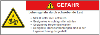
Like every other machine element, rothe erde® slewing bearings also require careful treatment. They may only be transported and stored horizontally. Ring bolts and load rings for such bearings are to be inserted into existing transport holes or fixed holes. In special cases, for example, inclined conveying, the interior is reinforced (with cross bracings). The bearing’s weight can be seen on the box or pallet. Radial shocks are to be avoided at all costs.
Delivery condition
Delivery condition

- Running system
The slewing bearings are delivered (as long as special lubricant or special amounts of lipids are not stipulated) filled with one of the types of grease (see table). - External surfaces
The external surfaces are preserved with Cortec VpCI 369/H10. - Gearing
The gearing is not greased. It is preserved as per the external surfaces.
Storage
Storage

- In covered storage areas
Storage is possible for approx. 6 months. - In closed, temperate (> 12°C) rooms
Storage is possible for approx. 12 months. - Outdoor storage
Storage is not permitted.
Longer storage durations require special preservation. After slewing bearings have been stored for a prolonged duration, increases in frictional torques can occur as a result of the sealing lip being suctioned. Carefully lifting the sealing lip slightly with a blunt object along the entire circumference, and rotating the slewing bearing 360° right and left, reduces the frictional torque to a normal value.
Installation
Installation
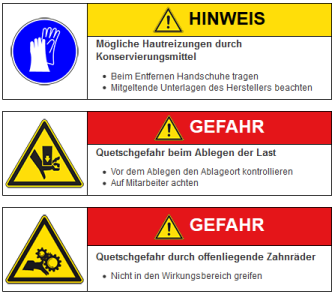
An even, grease- and oil-free contact area is a prerequisite to the successful installation of a bearing. Welding beads, feathering, colours and other irregularities have to be removed. The bearing rings have to be completely supported by the companion structure.
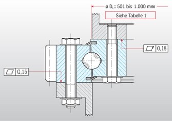
Example for evenness deviation in accordance with DIN EN ISO 1101
thyssenkrupp rothe erde recommends checking the contact areas with a levelling or laser device. This is offered as a service by thyssenkrupp rothe erde. The permissible values for evenness are shown in Table 1 below, entitled “permissible evenness deviations of contact areas in accordance with DIN ISO 1101“. The generation of peaks in small sectors is to be avoided. This means, the curve shape may rise and fall again within the 0° - 180° range only once.
Table 1:
Permissible evenness deviation of the contact areas in accordance with DIN ISO 1101
Permissible evenness deviation of the contact areas in accordance with DIN ISO 1101
| Circuit diameter in mm DL | Evenness in accordance with DIN EN ISO 1101 per contact area in mm for | ||
|---|---|---|---|
| MN 01 Double-row ball-bearing supported rings MN 08 Axial ball bearings | MN 06 Single-row ball-bearing supported rings Four-point bearings MN 09 Double- four-point bearings MN 23, 25, 28 Profile bearings* | MN 19 MN 13 Roller- bearing supported rings MN 12 Combination bearing | |
| up to 500 up to 1000 up to 1500 up to 2000 up to 2500 up to 4000 up to 6000 up to 8000 | 0.15 0.20 0.25 0.30 0.35 0.40 0.50 0.60 | 0.10 0.15 0.19 0.22 0.25 0.30 0.40 0.50 | 0.07 0.10 0.12 0.15 0.17 0.20 0.30 0.40 |
| MN is the abbreviation for model number and is comprised of the first two digits of the drawing number. For special designs, such as precision bearings with higher running precision and lower bearing clearance, the permissible values from table 1 must not be used. Please contact thyssenkrupp rothe erde for more information on this. *) For normal MN 25 bearings, double values are permitted. | |||
If the values are exceeded, it is necessary to mechanically process the bearing connection surfaces on the companion structure. The installation position of the slewing bearing must match that of the drawing.
The preserving agents can be removed with an alkaline cleaning agent. Do not let the solvent get into the seals or raceway. Clean the preserving agents from the slewing bearings’ upper and lower contact surfaces and gearing.
Note: The preserving agents can, for example, be easily removed using an alkaline cleaning agent.
Advantage: Fast removal of the preserving agent and minimal environmental impact.
Hardness gap
The unhardened part between the beginning and end of the raceway hardening is labelled with an “S” on the interior or exterior diameter of every bearing ring. On the geared ring, the hardness gap is marked on the axial area. The “S” gap part should be outside of the main load area on the ring with concentrated load. If the main work area for the application is known, the circumference-loaded ring’s gap part is to be positioned outside of the main loading area.
Gearing
Gearing
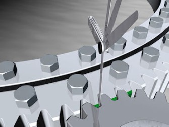
Measuring the flank clearance
It must be ensured that the tooth flank clearance is set at least at the 0.03 - 0.04 x module on the three teeth marked in green. After the final fixing of the bearing, the flank clearance over the entire circumference is to be checked. On the pinion, a tip edge radius and tip relief are to be provided.
Screw fitting/screw connection
Bearing and companion structure screw holes have to fit, otherwise inadmissible tensioning shall occur. Clearance holes are to be designed in accordance with DIN EN 20273 medium range.
| Thread/ Bolt diameter | Hole diameter | Tightening torque Nm for bolts belonging to strength class μG ≈ μK = 0.14 | |
|---|---|---|---|
| mm | for hydro. + electro. Md-bolts | for Md-key | |
| DIN EN 20273 | 10.9 | 10.9 | |
| M 12 | 14 | 137 | 123 |
| M 14 | 16 | 218 | 196 |
| M 16 | 17.5 | 338 | 304 |
| M 18 | 20 | 469 | 422 |
| M 20 | 22 | 661 | 594 |
| M 24 | 26 | 1,136 | 1,022 |
| M 27 | 30 | 1,674 | 1,506 |
| M 30 | 33 | 2,046 | 2,046 |
| Grade 8 | Grade 8 | ||
| UNC 5/8'' -11 | 18 | 286 | 260 |
| UNC 3/4'' -10 | 21 | 506 | 460 |
| UNC 7/8'' -9 | 25 | 803 | 730 |
| UNC 1'' -8 | 27.5 | 1,210 | 1,100 |
| UNC 11/8'' -7 | 32 | 1,716 | 1,560 |
| UNC 11/4'' -7 | 35 | 2,410 | 2,190 |
| Grade 8 | Grade 8 | ||
| UNC 5/8'' -18 | 18 | 320 | 290 |
| UNC 3/4'' -16 | 21 | 560 | 510 |
| UNC 7/8'' -14 | 25 | 902 | 820 |
| UNF 1'' -12 | 27.5 | 1,330 | 1,210 |
| UNC 11/8'' -12 | 32 | 1,936 | 1,760 |
| UNC 11/4'' -12 | 35 | 2,685 | 2,440 |
Fixing bolts
It is important to note the following points:
- Fixing bolts, nuts and discs (without surface treatment) normally belong in strength class 10.9, in accordance with DIN ISO 267.
- Adhering to the specified number and diameter is essential.
- Carefully tighten screws crosswise, in line with the specified values. The table above shows some reference values.
- The surface pressure under the bolt head or nut must not exceed the maximum limit.
- If the maximum pressure limit is exceeded, washers of suitable size and strength are required.
- The minimum screwing depth must be ensured for threads in blind holes.
- If a bolt tensioning cylinder is used, the necessary projecting ends of the threads for bolts or stay bolts is to be taken into account and appropriate washers are to be used.
Determining the tightening torque is not only based on the strength class of the bolts and the tightening procedure, but also based on the friction in the thread and contact surfaces between the bolt head and nut. The tightening torques specified in the table, “screw fitting/screw connection” above are guidelines which are based on lightly oiled thread and contact surfaces.
Dry threads require higher tightening torques whilst heavily oiled threads require lower ones. The values can, therefore, vary greatly. This particularly applies to threads for larger M 30, i.e. 1¼". From this size upwards, the use of bolt tensioning cylinders is recommended. In the event of insufficient friction connection safety, a friction value improver or form lock is required. Welding the slewing bearing is not authorised.
Lubrication and maintenance
Lubrication and maintenance

The lubrication nipples must all be easy to access, lubrication lines may have to be provided. thyssenkrupp rothe erde recommends automatic, centralised lubrication systems. The running system and the gearing are to be lubricated directly after installation. Here, and for every subsequent lubrication procedure the lubricants specified in the table below are to be used.
These raceway lipids exclusively include KP2K lipids, meaning lithium-saponified mineral oils belonging to NLGI class 2 with EP additives. The lubricants listed in the table for the raceway can be mixed together. The lubricants are listed in alphabetical order. Filling with lipids reduces friction, protects against corrosion, and is part of the sealing procedure.
Thus, always re-lubricate enough to ensure a grease collar made of fresh lipids forms around the entire circumference of the bearing gap or seals. Bearings are to be rotated or turned appropriately when lubricating.
Lubricants
Lubricants
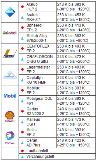
Table of lubricants and lipids
For lubricant-specific queries, please contact the relevant lubricant manufacturer. The lipids listed in the table have been approved for our slewing bearings and have been tested for compatibility with materials used by thyssenkrupp rothe erde for spacers and seals. The list of lipids is not exhaustive.
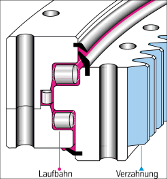
Profile of a bearing
If you use a different lubricant, please ask the manufacturer of the lubricant to confirm that it is suitable. The properties must, as a minimum, be in line with those of the lipids listed in the table and must be compatible with the materials we use. If using automatic lubrication systems, the lubricant manufacturer must confirm compatibility. Special lubricants are needed for use in low temperatures.
Lubricants pollute water. They must not reach the ground, groundwater or sewer system.
Lubrication interval requirements for the running system
- To be selected based on operating conditions
- For special requirements, please contact thyssenkrupp rothe erde
- In general, roughly every 100 hours of operation
- For roller bearings, every 50 hours of operation
- Shorter intervals between lubrication: In the tropics, in the event of high humidity levels, significant accumulation of dust and dirt, extreme changes in temperature and continuous rotational movement.
- For bogie bearings for rail and road vehicles, as well as bearings for wind turbines, special provisions apply.
In the event of downtime occurring between the installation of the bearing and it being put into operation, appropriate maintenance measures must be taken. For example, lubrication whilst the bearing is rotating after three months at the latest, or in further intervals of three months.
Re-lubrication is essential before and after any prolonged periods of the machinery being out of service. This is of particular importance in the case of service breaks during winter. When cleaning the device, it must be ensured that no cleaning agents damage the seals or penetrate the raceways. Seals are to be checked every six months.
Re-lubrication of the running system
The bearing must be re-lubricated when rotating or sufficiently pivoting until fresh lipids on the entire circumference leak from the seal lips or maze. It is the task of maintenance personnel to determine the individual supply quantities and intervals by checking the lubrication condition of the raceways in a targeted manner. Under extreme conditions, for example, in the tropics, in the event of high levels of humidity, significant accumulation of dust and dirt or extreme temperature fluctuations, levels of re-lubrication are to be increased and intervals to be shortened.
For bogie bearings for rail and road vehicles, as well as bearings for wind turbines, special provisions apply.
For partially-assembled bearings or in the event of downtime occurring between the installation of the bearing and it being put into operation, appropriate maintenance measures must take place, such as re-lubrication whilst the bearing is rotating or sufficiently pivoting after three months, at the latest, or in further intervals of three months. Re-lubrication is essential before and after any prolonged periods of the machinery being out of service.
Device cleaning
When cleaning the device, it must be ensured that no cleaning agents or water damage the seals or penetrate the raceways.
Re-lubrication of the gearing
We recommend automatic gear lubrication. The tooth flanks must always have a sufficient layer of lipids. It is the task of maintenance personnel to determine the individual supply quantities and intervals by checking the lubrication condition of the gearing in a targeted manner.
Note: Good lubrication is essential for the running system and the gearing. Only then can a satisfactory service life be reached.
Advantage: Optimum usage of lubricants and intervals increase systems availability
Checking the bolts
It must be ensured that bolt preload force is sufficient throughout the entire service life of the slewing bearing. Based on practical experiences, to offset settling, a re-tightening or re-tensioning of the bolts with the required tightening torque or preload force is recommended.
Testing the running system
Testing the running system
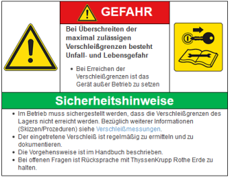
When the machinery is first put into operation, measuring the tilting clearance or reduction is to be carried out. It must be ensured that the bearings’ wear limits are not reached. We recommend repeating the measurement at appropriate intervals. In addition, a use lipid sample can be extracted and analysed.
Testing the sealing
Sealings must be checked at least every six months and if damage is detected, they must be replaced.
Disposal after use
Disposal after use

Disassemble bearings after use Lipid, seal and plastic parts are to be disposed of in accordance with the respectively relevant waste disposal guidelines. Bearings rings and rolling elements are to be recycled.
/thyssenkrupp_logo_claim_d.svg)
