Bearing inspection and wear measurement
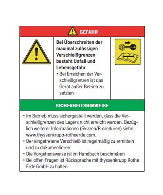
Safety information wear limits
Measurement of the tilting clearance
Measurement of the tilting clearance
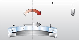
Picture 1: Tilting clearance measurement load principle (axial movement)
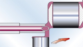
If possible, we recommend measuring the tilting clearance to determine the wear. The load principle for such a measurement is shown in picture 1.
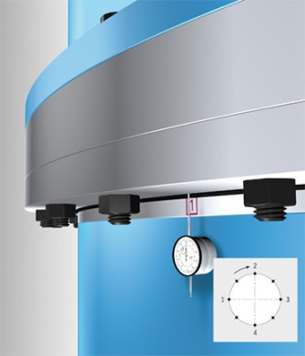
The area between the companion structure beneath and the bearing ring screwed onto the upper structure is measured (picture 2). In order to minimise the influence of the elastic deformation of the companion structure, the measurement must take place as close to the running system as possible.
Bearing inspection - preventing damage
Wear measurements make it possible to identify technical problems early, before these lead to unexpected systems downtime. This avoids unnecessary costs and expensive losses in production output. Thus, we recommend regular bearing wear measurements to evaluate the condition of the bearing.
A change in the axial movement or a drop indicate the wearing of the running system. This increase in wear can, depending on the application or bearing design, be determined by measuring the tilting clearance or the drop.
Picture 1: Tilting clearance measurement load principle (axial movement)
Implementing the procedure
- When the bearing is put into operation, a reference measurement is carried out.
- The measurement points are marked around the circumference from a specific position.
- For the zero setting of the dial gauges, which should have a measurement accuracy of 0.01mm, the maximum reverse torque is to then be started. Afterwards, a forward, tilting torque is to be generated, through load absorption if necessary.
- After the upper structure is swivelled around, the measurement is repeated in the marked measurement position (see table 4).
Maximum permissible increase in the bearing clearance (uniform wear)
Important: For certain applications (consult thyssenkrupp rothe erde), these bearing clearance increases are not permissible. This concerns, for example, 50% of the listed slewing bearings for rides.
Table 1: MN* 01, 08 (double-row ball bearings/axial ball bearings)
| Measurement procedures | Ball diameter (mm) | ||||||||||
|---|---|---|---|---|---|---|---|---|---|---|---|
| 18 | 20 | 22 | 25 | 30 | 35 | 40 | 45 | 50 | 60 | 70 | |
| Max permissible wear values up to mm | |||||||||||
| Subsidence measurement | 1.6 | 2.2 | 3.0 | 3.8 | |||||||
| Tilting clearance measurement | 2.5 | 3.0 | 4.0 | 5.0 | |||||||
Table 2: MN* 06, 09, 25, 23, 28 (ball bearing/profile bearing)
| Measurement procedures | Ball diameter (mm) | ||||||||||
|---|---|---|---|---|---|---|---|---|---|---|---|
| 20 | 22 | 25 | 30 | 35 | 40 | 45 | 50 | 60 | 70 | ||
| Max permissible wear values up to mm | |||||||||||
| Subsidence measurement | 1.6 | 2.0 | 2.6 | 3.3 | |||||||
| Tilting clearance measurement | 2.0 | 2.6 | 3.2 | 4.0 | |||||||
Table 3: MN* 12, 13, 19 (roller-bearing slewing ring)
| Measurement procedures | Ball diameter (mm) | |||||||||||||
|---|---|---|---|---|---|---|---|---|---|---|---|---|---|---|
| 16 | 20 | 25 | 28 | 32 | 36 | 40 | 45 | 50 | 60 | 70 | 80 | 90 | 100 | |
| Max permissible wear values up to mm | ||||||||||||||
| Subsidence measurement | 0.8 | 1.2 | 1.6 | 2.0 | 2.4 | |||||||||
| Tilting clearance measurement | 1.4 | 2.0 | 2.8 | 3.5 | 4.2 | |||||||||
Table 1: MN* 01, 08 (double-row ball bearings/axial ball bearings)
| Measurement procedures | Ball diameter (mm) | ||||||||||
|---|---|---|---|---|---|---|---|---|---|---|---|
| 18 | 20 | 22 | 25 | 30 | 35 | 40 | 45 | 50 | 60 | 70 | |
| Max permissible wear values up to mm | |||||||||||
| Subsidence measurement | 1.6 | 2.2 | 3.0 | 3.8 | |||||||
| Tilting clearance measurement | 2.5 | 3.0 | 4.0 | 5.0 | |||||||
Table 2: MN* 06, 09, 25, 23, 28 (ball bearing/profile bearing)
| Measurement procedures | Ball diameter (mm) | ||||||||||
|---|---|---|---|---|---|---|---|---|---|---|---|
| 20 | 22 | 25 | 30 | 35 | 40 | 45 | 50 | 60 | 70 | ||
| Max permissible wear values up to mm | |||||||||||
| Subsidence measurement | 1.6 | 2.2 | 2.6 | 3.3 | |||||||
| Tilting clearance measurement | 2.0 | 2.6 | 3.2 | 4.0 | |||||||
Table 3: MN* 12, 13, 19 (roller-bearing slewing ring)
| Measurement procedures | Ball diameter (mm) | |||||||||||||
|---|---|---|---|---|---|---|---|---|---|---|---|---|---|---|
| 16 | 20 | 25 | 28 | 32 | 36 | 40 | 45 | 50 | 60 | 70 | 80 | 90 | 100 | |
| Max permissible wear values up to mm | ||||||||||||||
| Subsidence measurement | 0.8 | 1.2 | 1.6 | 2.0 | 2.4 | |||||||||
| Tilting clearance measurement | 1.4 | 2.0 | 2.8 | 3.5 | 4.2 | |||||||||
Gearing check
Gearing check

Risk of crushing - Safety information
Over the course of the service life, inflow smoothing and gear wear occur. What constitutes a permissible wear limit value varies greatly from application to application. Experience has shown that the permissible wear can be up to 0.1 x module per tooth flank.
Subsidence measurement
Subsidence measurement
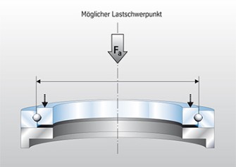
Picture 3: Load principle of the drop measurement
In cases where measuring the tilting clearance is not possible, we recommend measuring the drop. Here, the focus is on the load combinations inside the running tread diameter of the bearing. The load principle is presented in picture 3.
The area between the companion structure beneath and the bearing ring screwed onto the upper structure is measured (pictures 4, 5).
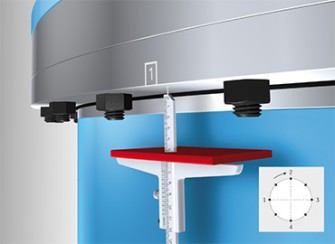
Picture 4: Basic structure of the drop measurement with depth calipers
The process is similar to that for measuring the tilting clearance:
- When the device is first put into operation, reference values are determined.
- The measurement points are marked around the circumference from a specific position.
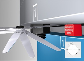
Picture 5: Basic structure of the drop measurement with feeler gauge
At appropriate intervals, after checking the bearing’s fixing screws, measuring the tilting clearance or drop under the same conditions should be carried out. The difference to the reference measurement indicates the level of wear which has occurred in the meantime. For rising wear values, measurements should occur more frequently.
Advantage: By clearly evaluating a bearing’s condition, worn parts can be replaced in good time. Together with optimal spare part management, this means damage and longer downtime periods can be avoided.
Note: If the permissible wear values are exceeded, we recommend the shutdown of the device.
The alternative: Integrated wear measurement equipment (IWM)
To further optimise the functionality and operational safety of the systems, thyssenkrupp rothe erde works incessantly on developing innovative solutions for the permanent monitoring of conditions. The integrated wear measurement equipment for slewing bearings is a patented invention. It allows for the online monitoring of the maximum permissible axial clearance or the drop of the slewing ring.
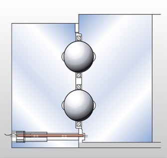
Picture 6: Wear measurement in a ball bearing
Advantage: Interruptions in operation are not necessary to record the axial clearance.
In the area of the peak load of the raceways, there is a pin made of stainless steel. This is electrically isolated and installed in a ring. The pin protrudes in a slot located in the counter ring. The maximum permissible clearance is configurable via the slot width.
If the clearance changes excessively, the ring and pin come into contact. A signal is triggered by the electric connection of the pin when the pin and counter ring touch. This signal indicates that the permissible relative displacement of the rings has been reached and that a bearing examination is necessary.
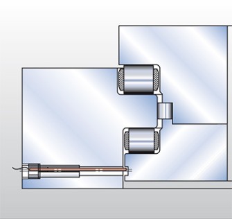
Picture 7: Wear measurement in a roller bearing
Advantage: The deformation of the companion structure, or elasticities of the screw connections do not significantly influence the measurement result.
The elastic approximation of the raceways, the axial clearance of the bearing, and the flatness deviation of the contact areas are balanced out. Costs for maintenance personnel are minimised.
Lipid sample extraction
Lipid sample extraction

Warning for possible skin irritation from preserving agents
Lipid sample extraction sets
Lipid sample extraction sets
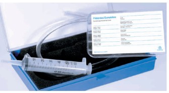
Picture 8: Lipid sample extraction sets
At the same time as the inspection measurements, used lipid samples are extracted. The used lipid analyses provide further information about the condition of the raceways.
Bearings with lipid extraction holes
Bearings with lipid extraction holes
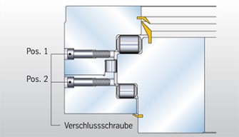
Picture 9: Triple-row roller-bearing slewing ring with lipid extraction holes
The lipid sample extraction set is made up of a plastic tube, various sealing caps, a suction device and a sample box for a maximum of five lipid samples, as well as an info sheet. The procedure is described in detail.
The grease samples must be extracted from the main loading zone.
The screw plug selected for the sample extraction (M16 EN ISO 4762) is removed (pictures 9 and 10: position 1 and, if necessary, opposite position 2).
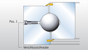
Picture 10: Single-row ball bearing with lipid extraction hole
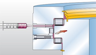
Picture 11: Extraction
Before extracting the lipid sample, cut the tube supplied at an angle (45°) so that it is slightly longer than the total length of the lipid extraction hole. The tube is then to be inserted in the appropriate hole up to the raceway area (picture 11).
Picture 12: Extraction details
The 45° cut surface must be positioned opposite the direction of rotation (picture 12)
The extraction holes are to be sealed again with the screw plugs.
After the extraction of lipids, the ends of both tubes are sealed again with plastic caps.
The lipid sample is numbered and filed in the labelled sample box.
The sample box is equipped with the necessary information (see lipid sample extraction set, picture 8) on the top.
Bearings without lipid extraction holes
Bearings without lipid extraction holes
Picture 13: Lipid extraction on the sealing lip
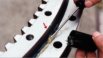
If there are no lipid extraction holes on the bearing, one or more grease samples are extracted from the seal. This area is cleaned near a lubrication nipple. Preferably, the extraction is to take place in the main work area and/or be offset by 180°.
During the re-lubrication on the abovementioned lubrication nipple (without turning the bearing), the leaking grease is extracted from the seal lips (picture 13). An amount of 3 cm³ is sufficient.
Note: Please carry out the extraction carefully in order to avoid the falsification of results caused by contamination.
Fe limit values
Fe limit values
Picture 14: Wear curves
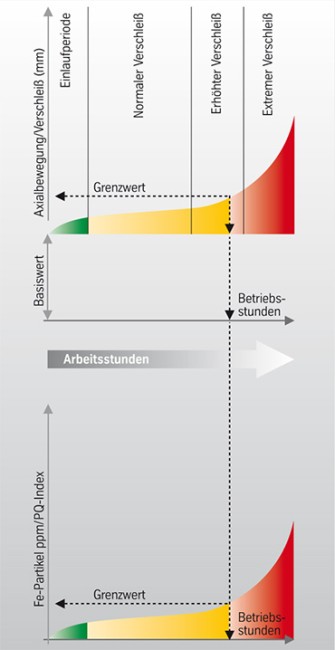
A limit value for permissible Fe contamination of the lubricant is to a large extent dependent on the operational parameters and re-lubrication intervals. The value can reach up to 20,000 ppm, depending on the application.
Wear curves
The diagram shows the increase in wear, more specifically Fe particles and the increase in PQ index based on operational hours (picture 14).
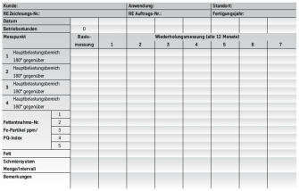
Table 4: Measurement table
Click here to enlarge
For standard applications, see values in tables 1-3. Upon reaching the limit value, please contact thyssenkrupp rothe erde.
The measurement and analysis values, as well as the bearing-specific information should be entered in a separate table (see table 4) and made available to thyssenkrupp rothe erde. Please send the sample box to thyssenkrupp rothe erde.
thyssenkrupp Rothe Erde GmbH
Service
Beckumer Straße 87
59555 Lippstadt
service.rotheerde@thyssenkrupp.com
thyssenkrupp rothe erde sends the lipid samples to a certified and qualified laboratory.
Advantage: Short processing times and provision of information on the analysis result and wear measurement via email
Request the lipid sample extraction set from the following address:
thyssenkrupp Rothe Erde GmbH
Tremoniastraße 5-11
44137 Dortmund
Phone number: (02 31) 186-0
Fax: (02 31) 186-2500
sales.rotheerde@thyssenkrupp.com
/thyssenkrupp_logo_claim_d.svg)
